Over the past couple of months I have been looking at inexpensive systems that teams could use to test their batteries. Below is a very simple prototype which can serve as the base of a pretty capable battery workstation. Hope it helps someone get started:) Sorry about the formatting I am new to this type of wiki layout.
One of the more confusing aspects of electrathon is battery selection and usage. The challenge is to be how to test batteries under electrathon usage conditions in a reproducible manner. Once we can conduct test reproducibly we can start to tweak individual aspects for optimal performance.
In testing, we face four issues:
What factors do we test for?
How do we test?
Cost of testing.
How do we Automate test?
After a few months of trial and error and feedback from some teams in Wisconsin, I would like to preset a prototype for a electrathon battery workstation which can be built for about $200 and some parts most team have laying around the shop.
Background
Basic charging is very straight forward. Just attach a 12V charger and let it run to completion.
Smart chargers charge more effectively by using three charge stage.
Charge at constant current until an upper voltage is reached.
Charge at constant voltage until a termination current is reached.
Continue to top off battery at a float voltage.
Finally, there are optimization chargers which allow the user to set charge variables such as charge voltage and charge current in order to optimize for a particular battery.
Basic discharging is also straight forward. Just attach a load such as light bulbs, power resistors, or even an electric heater.
As with charging, things get more complicated if one wants to precisely vary the load over time in order to compare batteries or one wants to automate the process in order to run 50 cycles of a test.
Monitoring
There are several systems available for monitoring and logging such as the Cycle Analyst. The RC world provides several solutions for controlling the process.
Project Specification
A power source.
A power sink.
An optimizing charger/discharger.
A laptop to control the process and log the results.
Power Source
To keep this prototype simple, in the charge part of the cycle we will use energy from a battery bank to charge our test battery.
Power Sink
To keep things simple, during the discharge part of the cycle we will used the energy from our test battery recharge our battery bank.
Side note - Relative Battery Capacity
We want to consider the relative capacity of our batteries. In order to fully charge and discharge our test battery our regenerative must be larger than the test battery.
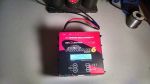
In this example, we use an Optima Redtop as the battery bank. The Redtop which has a capacity of about 24 Amp hours.
To prevent reversing polarity when connecting components, we will use polarized connectors called EC5 and battery clamps when working with large batteries.
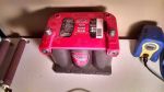
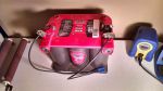
Charger
The next component is the charger. To meet our specification we need an optimizing charger. For this project we are going to use a Cellpro PowerLab 6 from Revolectrix. It meets all of our specification and can be purchased for around $180.
Side-note: I had trouble finding a suitable charge for this project. The choices seemed to be either a very expensive commercial charge system, a home built system, or this one.
The charger connected to the Source/Sink battery.
Laptop
The Cellpro charger can run in standalone mode. For ease of use we will connect the charger to a windows computer running the PowerLab software.
Test battery
For our test battery we will use a small 5 Amp Hour battery.
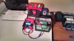
The Build.
Connect source/sink battery to source side of the PowerLab. If you have done it correctly the display on the PowerLab will light up.
Connect laptop to PowerLab with the usb adaptor and install the software. If you done it correctly windows will install the correct driver for the adaptor and the software will open
Connect test battery to output side of the PowerLab. If you have done it correctly the Cellpro software will detect that a lead acid battery has been connected.
-- Edited by dfarning on Sunday 23rd of August 2015 02:18:02 PM
I have been cycle testing a slightly larger version of this set up using a four battery regenerative battery pack with external power supply to keep the keep the regenerative pack from Discharging too Deeply for over a month while running a 50 cycle test on an Optima redtop to see how the performance degrades over time.
As luck would have it, the day after I send this post, something goes wrong and the Cellpro started limiting discharge capacity to five amps. My initial guess is that even though the system was operating well within its rate capacity, running 24 hour per day for weeks at a time was causing cumulative heat damage to the internal components and causing them to degrade. I'll look into it more.
There is a reason commercial battery analyzers cost thousands of dollars.