On my 3 wheel steer car I also want to have front suspension and for the past 2 weeks or so I have been trying out different designs.
I had 2 major goals for this, the first was to have a high pivot on the suspension so whenever the suspension is compressed the wheels actually move slightly outward from the car.
The other goal of mine was to make the suspension and steering handle independently from each other.
My first idea was to use a single swing arm. However the problem with this was I couldn't get my pivot arm from my steering to sit on the same circular arc as the suspension. So whenever the suspension is compressed the steering moves a lot ruining everything. I made 4 different designs with a single swing arm and I did make it better with each design but I couldn't get it as close as I wanted.
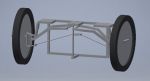
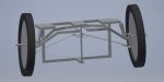
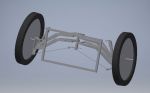
Eventually I gave up with using a single swing arm and decided to use a double swing arm. The nice thing about this is instead of everything thing needing to be on the same circular arc I would be able to use nearly any circle with the same radius for each part giving myself a lot of room. This would allow me to make the tie rods the same length as the swing arms making everything nearly independent. While with my last design I wasn't able to get it perfect I got it close enough.
Out of curiosity, how much suspension travel are you planning on having/needing?
I just completed my first full-suspension car and it only has about an inch of travel on both ends. Doesn't sound like much, but as I'm not planning on going off-road it should be fine. It seems pretty good on the test drives I've taken around my neighborhood.
So the largest problem with this design is I can only use a small part of shock's stroke. If I used all of the shock's travel in this current design it would be 3.27". I plan to limit the travel with a rubber block that can be moved on the car's frame to adjust the travel between .5" and 2" The reason for 2 inches is mainly just for the cocoa beach race which the really rough parking lot.
Can I ask why you want the wheels to move out when the suspension is compressed?
I ask because normally that is something suspension is designed not to do. The reason is because that outward motion causes scrubbing of the tire, which in turn causes drag and tire wear (a bad thing for Electrathon). It also causes a momentary side force as the suspension compresses and a similar (but less) side force in the opposite direction when the suspension returns to normal ride height. A suspension with this geometry will feel very skittish on a bumpy track, twitching left and right with every bump.
My biggest goal was for the suspension and the steering to be independent. If the wheel traveled in a path perfectly perpendicular to the the ground then when the suspension compresses the wheels would toe out. I could fix this by using a solid suspension axle, however this would not work with 3 wheel steering. All the suspension designs that I know of makes the wheel follow a circular or a elliptical axle path. Because of both of these reasons I know I would have some tire scrub when the suspension compresses. With the max 2" of suspension travel the each wheel will move about 1/2" outwards, and with 1/2" of travel the wheel will move .15" outward.
With the design of this suspension and steering system the swingarm's pivot must be inside the car. And if it was in the middle of the car then my legs would have no place to go. So at that point I had two options, high pivot and low pivot. A low pivot would move the wheels in, my thought is when the suspension would compress it will want to naturally move outwards, so if it would move inward with a low pivot that would create more tire scrub and it narrows the car making slightly less capable at turning hard. So with the high pivot it will make the car's track wider making it capable of turning harder and will put less stress on the car's suspension system.
Even if I could fit a pivot perfectly in the middle of a wheel's travel the wheel would still travel in a arc moving in/out from the car creating scrub.
If you went with something other than a swingarm front suspension you may have other steering options.
If you used a sliding pillar suspension with little or no steering axis inclination and a high mounted steering knuckle you should be able to avoid significant toe change with suspension movement.
...I think...
I just made a little mock-up of the suspension using a sliding pillar and with 0 degrees of king-pin inclination it works GREAT, with 1 inch of travel there is only a 0.19 degree change in the spindle. However with a 0 degree kingpin it will increase tire scrub. So I tried it with 20 degree kingpin inclination which is what I plan to use for me car and this created very different results with a 5.86 degree change in the spindle. So the question could almost be, how important is kingpin-inclination vs simplicity.
Both of these also require the steering knuckle and pivot arm be at the same height. If there is any offset between these 2 then there is a major change in the steering
As I recall, the Duck used zero kingpin inclination. How much scrub did you experience from that? I was under the impression that kingpin inclination (AKA steering axis inclination) had more to do with reducing steering effort than preventing tire scrub as it puts the axis of steering rotation directly under the contact patch of the tire.
If you really wanted to go crazy with it, you could use a steering rack and run your tie rods from opposite ends of the rack to each side thereby maximizing the length of your tie rods and minimizing the arc angle they experience during suspension travel.
Yeah, the Duck did have 0 kingpin inclination and it was really heavy to steer. However my original car used spindles from a kit car and 15 degrees kingpin inclination however I can not remember the tire wear on that. However in a season we only had 1 flat between the 2.
How I always thought of kingpin inclination is it allowed the car to turn on it's tires instead of an arbitrary line. Doing this would reduce tire scrub beacuse when turning the outside wheel won't have to move inwards sideways.
I still have a lot to learn on this this and only time will tell how it goes
With zero kingpin inclination the tires still won't have to move sideways when steering. They will just turn on a circle with a radius of the distance between the contact patch of the tire and the center of the kingpin. When turning left, the right tire will roll forward and the left will roll backwards. Or you could put them both on a solid axle with a center pivot like a wagon. Same sort of motion of the wheels when steering.
And I quote...
"Steering axis inclination
The steering axis inclination (SAI) is the angle between the centerline of the steering axis and vertical line from center contact area of the tire (as viewed from the front).
Effects of SAI
SAI urges the wheels to a straight ahead position after a turn. By inclining the steering axis inward (away from the wheel), it causes the spindle to rise and fall as the wheels are turned in one direction or the other. Because the tire cannot be forced into the ground as the spindle travels in an arc, the tire/wheel assembly raises the suspension and thus causes the tire/wheel assembly to seek the low (center) return point when it is allowed to return. Thus, since it has a tendency to maintain or seek a straight ahead position, less positive caster is needed to maintain directional stability. SAI adds positive camber while turning for both steering tires. A vehicle provides stable handling without any of the drawbacks of high positive caster because of SAI."
So from my interpretation of this, SAI allows the car to stay level during turns and make it physically easier to turn.
This now makes a lot more sense, my duck car actually leaned away for the turns with having 0 SAI.
Now i have to rethink my goals.
Ease in design/building vs ease in steering
If you run a single tie rod from the left steering arm to the right steering arm, that will give you the greatest length arc that you can get and minimize the bump steer on a sliding pillar design (with 0 degree SAI). You will need a single shorter tie rod to go from the steering shaft to either of the steering arms to enable steering control.
nickg that is something I never would have thought of, I just need to model it and see how it compares. It sounds like it would be a lot like a dual lever steering system. This system might even make 3 wheel steering easier.
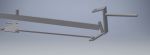
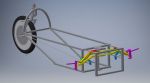
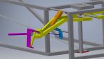
I have finnaly made some good progress on my steering/suspension setup. I decided to use a linkage on my suspension so I would be able to use all the shock and adjust my travel between .5", 1", and 1.5"
The reason I am have this slightly strange linkage is so that I can still have my high suspension pivot and not need to add height to mount the shock.
Its kinda hard to see how the linkage works but ill do my best to explain it;
When the yellow swing arm moves up it pulls on the dark blue linkage rod, the linkage rod then pulls the light blue suspension pivot, the suspension pivot then pushes on the orange shock.
I can adjust the wheel travel by moving the dark blue linkage rod on the light blue suspension pivot, right now it is set at 1" of travel. I can also adjust ride height by changing the length on the dark blue linkage.