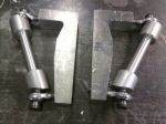
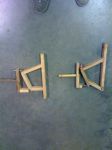
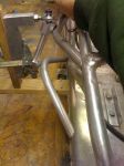
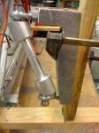
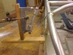
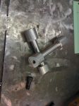
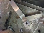
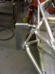
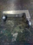
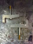
As of this year i have acquired a former students car, mike mcmurry (Centennial High School, car #50). He had a strange steering set up when i got it. It was designed to tilt the car in the direction of the turn. it didnt work out and tended to break alot. So this year i tore the steering off of the car after designing a new steering system. i did not get the car to lean like i had wanted to, but in turn i came up with a sysem that i am very satisfied with. while sitting in calculus one day with Nick Morrell, a fellow driver of from Centennial High School, and started doodling some designs. I came up with something a little to complicated to work, but after showing on one my peers, he helped me refine it to something that worked. right now i am in the process of cutting, milling, lathing, bending, and grinding for countless hours to get it ready to weld. after i had the drawings and was ready to start building the first of two prototypes (the first is on the left and the second on the right). the first model i built so that i could test different angles of "king pin" inclination, i put the quotes because with the steering system i designed i eliminated the king ping and now have two stationary pivotal points. after i found the best angle for tire lean, 25 degrees, i then started to tilt the entire system various degrees in the vice to figure out the best angle for more tire lean after adding positive castor (positive castor is when the upper pivot point is behind the lower pivot point), it came out to 15 degrees to the positive. after finding the 25 degree angle i built the second model to that measure, this time using ball joints instead on pins. this way when i put it back it the vice i could measure more presicely(?) the angle of tire lean i got. i measure the tire lean my putting a angle gauge on the spindle and recording the change in degree when turning left and right. i did this at 5, 10, 15, and 20 degrees. at 5 and 10 degrees the angle of tire lean was almost too small to notice but not non-existant. when i got to twenty degrees i ran into a problem that a few of the cars out there on the tracks today have, and that would be tire flop. tire flop is when the wheels lean into the corner, but lean too much and at low speeds the weight of the car will force the wheels to fall over jerking the steering wheel (or lever steering) violently. on the track this can be very dangerous because if out are not anticipating it you can become a hazard to other drivers coming towards you. at 15 degrees of caster i got 5 degrees of tire lean to the forward when on the outside of a corner, and 7 degrees to the rear when on the inside of the corner. this also causes the the inside tire to turn a few degrees sharper than the inside. i dont know how to explain this but i know that you want the inside tire to turn a little bit sharper because when turning a corner the tires travel on different paths. the inside tire on a sharper radius than the outside. after building the prototypes i started on the actual steering system. i started with the parts the pivot points are mounted too. i took a solit 1 1/2" solid aluminum. i turned the center down to 3/4" to save a bit of weight. then milled a block of aluminum into the "L" brackets you see in the close-up. the angles on the round stock are at 25 degrees to compensate for the 25 degrees of "king ping" inclination to creak clearence for the ball joints. then i made a wood stand to mount the assemble to the position they will be mounted on the car. then i proceeded to bend and grind aluminum tubing fitted to mount the assembly to the car... at this point i am currently still in the process of bending my last piece of tubing and weld it to the frame..
if anyone would like to make a few suggestions please feel free. be considerate as i am also learning as i go.
Looks good. How do you plan to attach the bolt to the "L" bracket for the wheel? Is it similar to the second picture? Also same question about the steering arms.
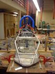
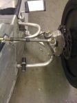
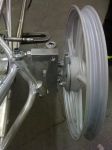
Trevor based his steering off of my car #59, so I think he's going to do something similar to what I did. Correct me if I'm wrong Trevor. Here's a photo of my car's front suspension
Trevor, for the 5/8" bolt that is going into the spindle, is that going onto the moped front wheels? Or is it different front wheels altogether? Thought I might ask.
the 5/8 bolt will be the spindle. and i am still using the moped from wheels. since half inch spindles seemed to be breaking on some cars. i have a question for everyone reading this... would it be better to press the bolt in over the threads and leave the head of the bolt on? or cut the head of the bolt off and press it in threads last? the bolt it only threaded about an inch and a half and the bolt is 6 and a half inches long
Trevor, for the 5/8" bolt that is going into the spindle, is that going onto the moped front wheels? Or is it different front wheels altogether? Thought I might ask.
Zaine
Zaine,
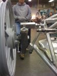
We milled out the moped wheels to accept larger bearings.
I have often thought about doing this but it did not look like there was enough 'meat' on the shoulder to allow a bigger bearing and have strength left to keep the bearing from expanding the hole and becoming loose. What is the O.D. of the 5/8" bearing you are using??
I have often thought about doing this but it did not look like there was enough 'meat' on the shoulder to allow a bigger bearing and have strength left to keep the bearing from expanding the hole and becoming loose. What is the O.D. of the 5/8" bearing you are using??
Mike,
Maybe Mark will see this and post the size. I know it was a very common bearing. Memory says it was a cut of about .020 to upsize the hole.
the 5/8 bolt will be the spindle. and i am still using the moped from wheels. since half inch spindles seemed to be breaking on some cars. i have a question for everyone reading this... would it be better to press the bolt in over the threads and leave the head of the bolt on? or cut the head of the bolt off and press it in threads last? the bolt it only threaded about an inch and a half and the bolt is 6 and a half inches long
I would try and press the bolt in over the threads and leave the head of the bolt on. But I haven't ever pressed a bolt through something so it may not be the best way. One thing I would check is if the threads on the bolt are the same circumference as the rest of the bolt, it's probably the same but maybe something to check. The reason I would leave the bolt head on is to have a better area to secure it if it was to move (weld a piece over it). But I also have no experience with this so maybe it wouldn't be able move.
The bearing # 6202Z ID .625 OD1.384 Purchased from McGuire bearing in portland OR . We had Aaron williams son who happens to be one of my EX students machine out the rim. I do not have any machines big enough to do the work. Also I know Kenny would do it right.
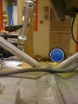
I drilled and tapped my aluminum spindle mounts to accept the 20mm bolt that fits my front wheels. Then faced off the inside part where the tread was sticking out from so I could put a washer, castle nut, and clip to keep the castle nut from vibrating off during a race.
If you were wondering how I did it Trevor, there you go.
we decided we are going to press the bolts in over the threads, after milling out a slot in the "L" bracket, for the bolt head to counter sink into so it wont turn.
i should have the majority of it dont by the end of the week. i have to get someone to wle dthe rest of it that knows what they are doing. since one peice in solid 1 1/2 inch aluminum and the other is very thin tubing. i will deffinately have more pictures for you guys though.
i have all the welding i need done on my car. i got the holes drilled for my axles. i drilled them at 39/64ths, and im going to press my 5/8ths axles in tonight feedback?
I am new to all of this. I am Trevor Cathcarts dad, The whole Centennial team is doing a great job with there cars. The first race is just around the corner. I am looking forword to see how the new front steering setup on car #50 is going to work. he did a fantastic job in building it.
my car is almost completely finished. all that i need to do is get some sides on it and im done.. it doesnt turn as sharply as i would like but it will still work.. after all we only turn a few degrees at a time.
yes i still have the back one and i will put them on soon i raced today at MHCC and got 6 laps in before i rolled it over and destroyed the motor:/ my next project is to replace it and build a cage for it then clean up the wiring. congrats to alex chiodo12 and derek ingwood25 for 1st and 2nd respectively