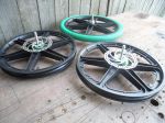
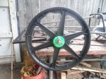
Wheels I got (3) plastic BMX bicycle mag wheels ...(2) fronts (for the front) ...& (1) rear (for the rear)
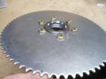
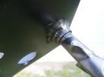
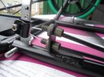
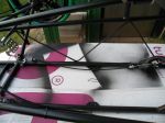
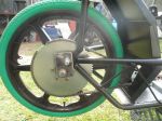
The rear wheel has a threaded on freewheel unit, that I added a 72T #35 sprocket to Here's how its attached/installed on the freewheel unit
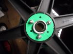
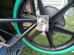
Rear wheel with freewheel unit & sprocket installed
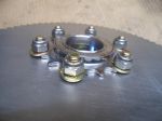
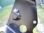
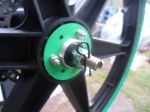
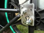
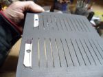
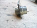
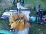
The front wheels didn't have threaded hubs ...so, I made up some "hub rings" ...& bonded (using Loc-Tite) on some 48mm brake rotor hub adapters ...& then, bolted them on (using (3) 3/16" x 3" Stainless Steel bolts) for added strength & hopefully increased durability
Here is the other side
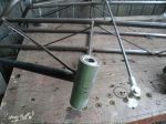
Bearings
I also, removed the stock bearings, races & 3/8" axles from the wheels ...& then, installed some R8RS bearings
*These bearings have a 1/2" ID for upgrading to 1/2" axles (as per the rule book)
I had to use some .025 shim material to get the bearings to fit "snuggly" in the hubs
...& also, used some Loc-Tite High Strength Bearing Retainer, to "glue" them in
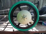
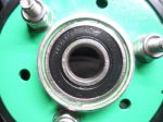
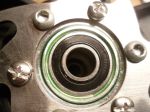
Here is a front wheel (with bearing installed)
Rear wheel (with bearing installed)
After assembly, I inserted some 1/2" bolts, to make sure the bearings would set properly &/or squarely, with each other
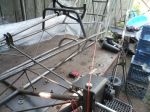
A piece of string (ran from the middle of the rear axle up thru/over each king pin) helped to establish the Ackermann angle, necessary for good steering geometry
...& so, I painted up some of the wheel "hardware" (sometimes little details make a big difference)
For reference, here is an excerpt from the official Electrathon Rule Book
9 BRAKES and AXLES 1. At least two wheels must have brakes. 2. Brakes must be fitted to two wheels of the same axle. Either both front wheels or both rear wheels depending on vehicle construction. 3. The two brakes must have separate actuation cables. If both brakes are to be actuated by a single hand or foot lever then both cables should be attached to the lever. 4. Regenerative braking is permitted in addition to conventional brakes. 5. The vehicle must not roll if pushed while brakes are applied. The vehicle must also be able to demonstrate a straight stop from a speed of 25 MPH in less than 40 feet. 6. Axles supported at both ends must have a diameter of at least 3/8"(10mm). 7. Axles supported only on one end must have a diameter at least ½"(12mm) 8. Safety wire or cotter pins must be used to secure cantilevered wheel axle nuts. Nylon lock nuts and double nuts alone are not acceptable
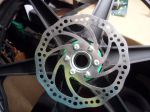
With Rotors on both front wheels ...& Calipers on both Spindles ...it looks like we've got #1 & #2 "covered"
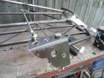
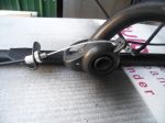
To comply with #3, I made up a dual brake cable attachment "piece", that works with the dual brake cable mount, to connect both cables to the brake pedal
The upgrade to 1/2" axles helped us comply with #7
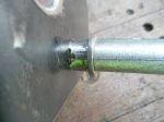
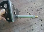
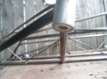
...& then, to comply with #8, I used a couple of 1/2" rod Pins (from a riding lawn mower) in conjunction with a couple of 1/2" Loc-Nuts, to mount the front wheels
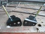
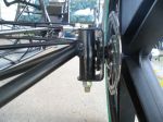
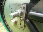
I incorporated some of the RS bearings into the spindle tubes (I think they are also, refered to as Boss Tubes) ...& used some 1/2" x 5" Grade 8 bolts (for good-n-strong King Pins)
Upper Spindle Bearing
Lower Spindle Bearing
I also, used bearings on the Steering Shaft which, along with the Spindle Bearings, should give us some nice-n-smooth, steering action
A friend brought to my attention his concern about having the brake cables connected to the brake pedal vertically (one over the other)
He thought that the upper cable could/would be pulled on quicker &/or harder than the lower cable, causing a dangerous, uneven braking situation.
...& thought that it would be better, if the cables were connected to the brake pedal, horizontally (next to each other)
After thinking it thru, I told him that "if" the cables were connected, directly to the brake pedal vertically (one over the other)
...the brake pedals mounting bolt, would be the fulcrum
...& so yes, the upper pedal could/would be pulled on quicker or harder (because the upper cable would be further away from the fulcrum, than the lower cable is)
But
I think that when I incorporated the dual brake cable connector
...the fulcrum moved from the brake pedal bolt
...up to the dual brake connectors bolt
&
Since both brake cables are connected at the same distance from the fulcrum
...they, should get pulled on evenly
Here is another excerpt from the (official) Electrathon America Rule Book
12 ELECTRICAL SYSTEM 1. A fuse or circuit breaker is required in any electrical circuit between the battery and any electrical device. 2. All fuses or circuit breakers should be mounted as close as practically possible to the source of power. 3. All fuses or breakers should be sized to protect the wiring to which they are connected. The current rating of fuses and breakers shall be no more than those listed in the adjacent table for standard automotive cable.
13 ISOLATION SWITCH 1. An isolation switch (kill switch) is required on all vehicles. This switch must have a break current rating that exceeds the maximum current draw of the vehicle. 2. The switch must be located in the main positive power cable between the battery and any motor controller. 3. An actuator may be attached to the switch for remote operation provided that it is durable and reliable. 4. Means must be provided for both the driver and race officials to actuate an isolation switch. 5. The driver must be able to actuate the switch while in driving position and without reaching outside the vehicle. 6. Race officials must be able to actuate the switch from outside the vehicle without reaching in. 7. Two switches may be installed if necessary. 8. A circuit breaker may be used as the isolation switch. 9. The switch or actuator accessible from outside the vehicle must be mounted within a solid red triangle whose sides are at least 4 inches and in contrast to vehicle color or graphics. 10. Wiring must be well insulated and securely attached to the frame or body. All wiring must be kept free from moving parts and protected from chafing. 11. Wiring that passes through a hole with sharp edges or through sheet metal must be protected by an insulating grommet or other suitable device. 12. Terminals must be secured so they will not come loose or short out during a competition. 13. No part of the electrical system may use the vehicle frame as a conductor. The frame must not be grounded.
I'm going to use a 48V 50A Circuit Breaker as a re-settable fuse
...& Isolation Switch (to comply with #1 & allowed by #8)
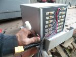
I made up a mounting bracket to hold the Circuit Breaker ...& a small Voltage Meter too
* The meter will be wired so, it will be "on", when the CB is "on" to indicate that the system is "powered up" or "live" ...& also, display the systems current voltage level
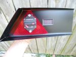
To complywith# 9, I rounded up a scrap piece of red vinyl
...cut it into a ~4" triangle
...& installed it under the CB
...but then, my friend mentioned that the Red Triangle isn't solid red
-- Edited by Functional Artist on Tuesday 3rd of October 2023 12:32:45 PM
A friend commented that "where you have the "safety pins" located, could/will allow the nut to come loose up to ~1/4"
So, I double checked in the Rule Book
9 BRAKES and AXLES 8. Safety wire or cotter pins must be used to secure cantilevered wheel axle nuts. Nylon lock nuts and double nuts alone are not acceptable. (page 8)
I was thinking that the intent of the "safety wire" was to make sure the retaining nut could not unthread all of the way, whereas the wheel could actually come off of the vehicle & I'm not sure if having a wheel simply "come loose" would be considered a safety thing ...whereas a wheel actually coming off definitely would be But, Then, further back in the rule book, under Vehicle Design Guidelines, it actually says to "use an axle bolt and nut that accepts a cotter pin"
AXLES One important note: DO NOT USE BICYCLE OR MOPED AXLES UNLESS SUPPORTEDAT BOTH ENDS. If your axles are cantilevered (attached on one side only like a wheelchair) you MUST replace the stock axle with a 1/2" or12mm diameter bolt. Axle diameters less than 12mm are illegal. A bicycle or moped axle WILL break. It is easy to pull out the stock axle and replace it with a larger one. You must replace the wheel bearings with cartridge bearing assemblies. These can be found at bearing supply stores. Use an axle bolt and nut that accepts a cotter pin so your wheel doesn't come off. This is a rule requirement. (page 23)
So, what (if any) is the difference between "Rules & Guidelines" in the Electrathon America Rule Book?
...& would the Safety Pins, I have on Polaris, pass an inspection?
Powered by: (I'm going to try/test a few different battery packs) ...1st test - (4) 12V 12AH SLA batteries (~8 lbs. ea. so ~32 lbs. total) ...2nd test - (4) 12V 17AH SLA's (~10lbs. ea. so ~40 lbs. total) ...3rd test - A custom built 14S 48V 15AH Lithium module (made of 3.7V nominal pouch cells)
Other specs: Wheels: 20" BMX bicycle wheels with a ~61" circumference Gear Ratio: 7.2:1 (10T drive sprocket & 72T driven sprocket) Chain: #35 pitch
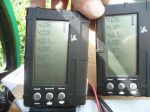
Power Meter: PZEM-051 Speedometer: Cell Phone with speedometer app
To get an estimate of what speed a set up like this might produce I use my Ball Park Equation
Motor Speed/Gear Ratio=Axle Speed x Tire Circumference = Inches per Minute traveled/Foot(12) = Feet per Minute traveled x Hour(60) = Feet per Hour traveled x MPH Multiplier(.000189) = Miles Per Hour
Here is the math, using the above specs: 3,000 (Motor Speed or RPM's) divided by 7.2 (Gear Ratio)= 416.67 (Axle Speed or RPM's) 416.67 (AS) x 61" (Tire Cir.) = 25,416.87 (Inches per minute traveled) 25,416.87 (IM) divided by 12 (Inch per Foot) = 2,118.07 (Feet Traveled per minute) 2,118.07 (FM) x 60 (Minutes per Hour) = 127,084.20 (Feet Traveled per hour) 127,084.20 (FH) x .000189 (mileage multiplier) = 24.02 MPH
IMO getting a top speed of ~24 MPH out of a prototype kart
...running on plastic Bicycle wheels
...& powered by a 1.2HP motor, seems like a good place to start our testing
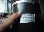
AS I mentioned, the motor I'm using is a MY-1020 48V 1,000W brushed motor (~1.2HP) (currently ~$100.00)
...with an average 20A draw (1,000W/48V =20.83A) & The Speed Controller is a Mode1: YK31C (I think that (1) should be an "L") ...Chinesium? (currently ~$30.00)
&
Thumb Throttle (currently) ~$10.00
So, the whole "propulsion unit" is only ~$150.00
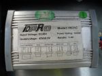
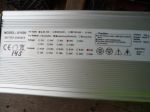
YK31 Speed Controller Specifications:
Rated Voltage: 48VDC (means that it's for use with 48V systems) Power Rating: 1,000W (means that it's for use with up to 1,000W motors) Under Voltage: 42V+/- 0.5V (means that the controller will "shut the system down" at ~42V to protect the battery pack) ...& the +/- 0.5V (means that there is a 0.5V variable so, it will shut down somewhere/anywhere in between 41.5V & 42.5V) Handle: 1-4V (means that the controller is set up for use with a 1-4V Hall Effect type Throttle)
Connections:
Speed Adjustment: Connect to the Throttle Brake: (signal) Connect to the Brake light switch Indicateor light: Connect to the Voltage meter (more Chinesium?) Electric Lock: Connect to the On/Off switch Motor: Connector to the motor Battery: Connect to the battery cables
* Not shown are the connectors for the Brake light & also, the Charge Port
Quote from the previous video: "I think we "smoked" that motor"
FYI: Last summer I first tried testing that little 48V 1,000W motor, on my Hell-raiser kart ...powered by a 48V 400A Kell controller (instead of the proper size 48V 20A controller)
The kart zipped right along (~26MPH top speed) ...was very peppy ...& even did a couple of donuts (~2.55) ...but then, flames started shooting out of the ventilation holes, of the motor (~3.25)
So, I was just trying to see if I could get a little bit "more" out of it, on this kart ...but, I guess NOT
So, don't blame the motor ...that one, was "my bad"
Hey Archer, Thanks! Yes, I'm working on a solution that will include Castle Nuts ...& also, trying to get a bit more ground clearance
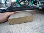
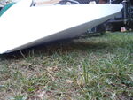
Right now, it sits at ~1 3/4"
...so, it'll "clear" a 2" x 2"
...but, that height isn't realistically feasible for testing, on my "neighborhood test track" Besides scraping & potentially damaging the chassis ...& to make things worse, "bottoming out" causes the kart to lose traction ...be it, propulsion traction, steering traction &/or braking traction (they are all bad)
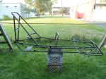
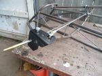
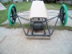
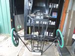
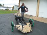
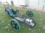
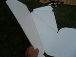
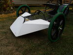
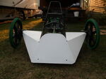
Here's the front of the kart
So, yea, it's really low
...& so, no testing until I can gain some more ground clearance
* It would have been so much easier to "raise" the chassis "if" I would have incorporated a suspension system ...just adjust the coil-over shocks
Keep in mind that this was from a 1,000W motor with a ~20A rating ...& I made it output ~5X it's "factory specified book rating"
If you thoroughly analyze the data in the Hell-raiser Maiden Voyage video (posted previously & it's a wealth of "real world" data) you'll see that, when I first took off from a dead stop ...the meter showed that (1,000W) motor was registering as ~5,000W ...& the corresponding Amperage draw was ~108A (see video @ ~1:40)
Then, further along in the video, when accelerating out of a turn ...the motor registered as ~5,800W ...& the corresponding Amp reading was ~122A (@~2:15)
Later, when I "punched it" @~3:25 is when the flames started shooting out ...& I just happened to get it on camera
Now for comparison, I tested the same 48V 1,000W MY-1020 motor (& same (4) 12V 12AH SLA's) on my Excalibur kart
...but, "ran" it with the proper YK-31 (~20A) speed controller
Notice in this video (another wealth of "real world" data) that upon first "take off" or hard acceleration (@2:02)
...the motor registered as 1,644W (on the meter)
...& the corresponding Amperage draw was ~34.45A
Then, At (2:04) the motor registers as ~1,712W ...& the amp draw was ~37.69A
The highest numbers that I saw were ~1,760W (@~2:05) & ~38.26A
Even, upon accelerating out of a "donut" (@~4.:56) ...the motor registered as ~1,701W ...& the Amp draw was ~37.77A
* So, it looks like these MY-1020 motors will put out a bit more power, than they are rated for
...but, if you overload them, too much, they will "burn out"
To take it one step further & collect more data, I installed a second 48V 1,000W MY-1020 motor ...a YK-31 SC ...(4) brand new 12V 15AH SLA batteries ...& took it for another ride (& recorded some data)
Assumptions: First of all, I assumed that having (2) motors, would make it go faster ...but, it didn't
Secondly, I thought using (2) motors, the data would double (Wattage, Amperage & Voltage drop) ...but, they didn't either
Here is a quick comparison of some of the data Single motor Take off Wattage: ~1,644W Amperage: ~34.45A Voltage drop: ~6V
Dual motors Take off Wattage: ~2,400W Amperage: ~52.12 Voltage drop: ~5V
So, I'm thinking that the (2) motors worked together ...so, neither one of them, had to "carry" as much of the load & As such the power usage was more than what just (1) motor alone would require ...but also, wasn't double what a single motors numbers were either
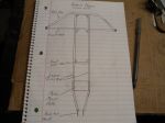
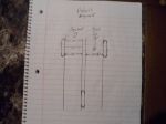
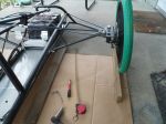
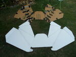
I figured the rear wheel is pretty much "fixed" ...so, I worked off of it, to align the front wheels (left side of drawing) ...& then, "Toe" the front side, of both of the front wheels, inwards ~1/8" (right side of the drawing)
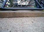
I set the kart on a big piece of cardboard to help set & illustrate the alignment
First, squared the front wheels with the rear wheel
Your alignment method looks good. I would suggest making a 'steering lock' that lets you lock the steering wheel dead straight when doing alignment. We normally paint it orange to remind us to take it off before driving.
Next write down a couple of measurements such as back of front wheels to frame and front of rear wheel to frame.
Then if there is an 'incident' at the track, you can throw on the steering lock, check your measurements and reset the alignment quickly with just a tape measure.
Hey Archer,
Yup, that seemed like the best wat to do it.
Hey Pro EV,
That's a great idea
...simple to use & should give very consistent results.
Have a pic or example of this "steering lock"?
* Using ~1/8" of toe in is common practice in the go kart world
This adjustment usually helps the steering wheels, "work together"
...so, the steering (& kart) doesn't feel so "squirrelly"
...& also, helps the vehicle goes straighter, down the road, with less effort.
** The steering on the Polaris kart seemed to be functioning pretty well, on that first test ride.
Zero toe offers the least rolling resistance, so it seems a good place to start. If there is any give in the steering system, a small amount of static toe in (like 1/32 or 1/16) might give zero toe when in motion. Toe out helps with turn in. Toe in helps with stability in a straight line.
Looking at your design, I do not see an easy way to 'lock' the steering. Making a mark on the steering shaft and the bearing? might be a way to get a close to exact repeatable steering position.
"Toe out helps with turn in."
I've never heard of this, could you please explain further?
* I've had to "fix" the steering on a couple of go karts, that had the wheels toed outwards (they were difficult, unpredictable & sometimes scary to drive)
...but, after aligning the wheels
...& then, toeing the front wheels inwards, a little bit
...they seemed to drive much better
** The way I squared the steering wheel, was to measure from the floorboard, up to the top of each side of the steering wheel (19 5/8")
...& then, used a bungy cord to "lock" it in place, while adjusting the tie rods.
Analyzing the data from the last test run video, the Voltage drop on these (4) 12V 20AH SLA's seemed to stay pretty consistent, at ~3V
While cruising at top speed, with a WOT, it looked like the average wattage reading was in the ~500W - 700W range ...with corresponding amperage readings of ~10A - 15A (ex: 580W & 12.13A @2:32)
Then, accelerating out of a couple of turns, I saw 1,127W & 23.4A (~2:46) ...& also, 1,316W & 28.5A (~6:00)
The highest readings that I saw was 1,555W & 34.8A (~13:32) accelerating out of another turn
* It seems like the numbers (W & A) rose a little bit over the course of the test (maybe happens as the motor warms up? or maybe, as the voltage level in the battery pack decreases?)
The acceleration seemed good
...& it looked like the top speed increased from 22MPH (in the first test ride video) up to 23MPH
...maybe due to being a bit more aerodynamic, because the CAD hood?
Listening to the motor & drive train, when accelerating, the "wind up" sounded good ...it didn't sound like it (the motor) was ever struggling ...but also, at top speed it didn't sound like it was "winding out" & you felt like you needed to "shift up" to a higher gear
It looked like, during this ~20 minute test
...we drained ~110Wh out of the battery pack
...traveled ~4 miles
...had a top speed of ~23MPH
...& the average speed was ~11MPH
The kart seemed to perform pretty well (& as anticipated) overall
...the chassis felt firm without any noticeable flexing
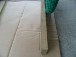
...the seat was comfy & held me in place pretty good
...the steering was pretty easy to maneuver (drove (1) handed most of the time while holding the camera)
...the alignment seemed good didn't notice much if any "scrubbing" & it seemed to coast pretty well too
** Let me know anything I might have left out
...&/or anything you guys may have noticed
*** Another thought about steering "toe in"
I was thinking where a term like "toe in" would have come from (or where I'd heard it before)
IIRC it's a Skiing term
...& they say that you need to keep your big toes (& front of the ski's) pointed inwards a little bit, which will help you to go straight (in this analogy, the ski's would be the wheels)
...& "if" you don't FWIU (I'm not a skier) things can get all "squirrelly" & hard to control. (& then, hello Mr. Tree)
I have been looking around to try & find out/understand why the front wheel "wobbled around" &/or "acted goofy" a couple of times, on the last test ride. ...& it looks like the steering shaft is flexing in the middle (~1/2")
So, I inserted a solid rod, inside of it, to help stiffen it up ...but, I may have to install a center support, we'll see.
"Toe out helps with turn in." I've never heard of this, could you please explain further?
* I've had to "fix" the steering on a couple of go karts, that had the wheels toed outwards (they were difficult, unpredictable & sometimes scary to drive) ...but, after aligning the wheels ...& then, toeing the front wheels inwards, a little bit ...they seemed to drive much better
** The way I squared the steering wheel, was to measure from the floorboard, up to the top of each side of the steering wheel (19 5/8") ...& then, used a bungy cord to "lock" it in place, while adjusting the tie rods.
With Toe In, both front tires are trying to center the car. They are constantly working against each other to keep the vehicle straight. This tends to make the vehicle 'stable' or 'dull' depending if the driver likes it or not.
With Toe out, both front tires are constantly loaded to turn outwards. The vehicle tends to wander down the straight as the load between wheels fluctuate. The steering is either 'all over the place' or 'sensitive' depending on whether things are going well or not.
Going into a turn, the toe out helps the car respond instantly to turn in to the corner, since the inside wheel is already trying to turn the car. When a driver is unhappy with initial turn in response, this is a quick fix.
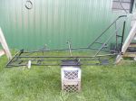
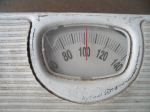
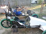
I removed the (4) 12V 20AH SLA's, to move on to test/try a 14S 48V Lithium battery ...& while I had the battery pack removed, I went ahead & put the kart on a scale
Looks like the entire kart (without battery pack) weighs just a bit over 100 lbs.
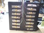
I assembled a 14S 48V ~15AH Lithium battery pack, out of (14) Chevy Volt (gen 1) Lithium battery cells
I made/used a DIY plastic top, as a cell holder
During assembly, I also, installed individual BMS (battery monitoring system) "leads" to every cell
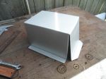
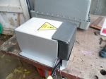
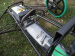
Then, I made a steel box to contain the pack & help protect the cells
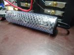
I mounted a shunt (sends data/info up to the PZEM-051 power meter, on the dashboard) inside of a piece of vinyl tube (to insulate it from...everything)
...& mounted "it" inside of the box
* Notice there are (3) "sets" of wires coming out
On top are the shunt connectors
In the middle are the (2) (10g.) battery cables & XT90 connector (used for charging & discharging)
On Startrek, The Next Generation, there was a highly functioning android (robot) named Data ...& when someone asked him, "how he was doing today?" ...he would respond with "operating within specified parameters" (meaning "I'm fine" & everything is working as it should)
I try to practice & use this concept, when working with many things (especially electrical systems) ...but, first you have to know what the limitations, of a situation are, to be able to establish &/or set some parameters
For example:
The (4) 12V 20AH SLA batteries (that I used in the first test run)
Voltage Range These SLA's have a safe usable voltage range of ~13.5V (high) down to ~10.5V (low) ...so, each battery has a ~3V of usable voltage ...& for the pack (as a whole) the voltage range is ~53V (high) down to ~41V (low)
* Which gives us a usable voltage range of ~12V
Current The 20AH rating, means that they are rated, to be able to put out ~20A for 1 hour ...or ~40V for ~1/2 hour ...or (taking it the other way) ~10A for ~2 hours
* So, these batteries can be "safely" discharged at ~20A ...drawing less than 20A, would be better ...& drawing any more than that, is "getting out of the specs"
Capacity If discharging at ~20A (the max current draw, during that 1st test run, according to the meter) the Max discharge (like we subjected these batteries to) ...would be considered a 1C discharge rate ...& the average draw (during that run) was in the ~10A - 15A range (which would be a .5C - .75C rate)
So, the parameters for this pack would be: ...do not recharge it above ~53V ...do not discharge it below ~41V ...& it would be best to try & keep the current, drawn from it, in the ~20A (or less) range
* Feel free to comment &/or add anything pertinent, or that I may have left out
Next, let's discuss the parameters of the 14S 48V ~15AH Lithium battery pack (that I assembled for Polaris)
The LG Chem (gen 1) cells (out of a Chevy Volt) have a "safe" usable voltage range of (low ~3V) up to a (high ~4.15V) per cell
So, (14) of these cells, connected together "in series", would create a 14S 48V 15AH Lithium battery pack ...with a "safe" usable voltage range of (low ~42V) up to a (high ~58.1V)
...have a ~15A C rating
...contains ~735Wh of energy ...& weighs ~12lbs. (cells only, not including the box)
So, the parameters for this 14S 48V ~15AH Lithium pack would be:
A "safe" usable voltage range of ~16V as long as we:
...do not recharge it above ~58V ...do not discharge it below ~42V ...& it would be best to try & keep the current, drawn from it, in the ~15A (or less) range
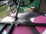
I made a center support for the steering shaft (to keep the steering shaft from flexing in the middle)
* Adding a bearing or bushing in the middle of a shaft, isn't the easiest thing to do ...because, "if" the bearing isn't pretty well centered, on the shaft (in between the other (2) bearings) it will cause resistance
Especially if welding the bearing holder "in place" ...because when welding, it "draws" the (2) pieces of metal together a little bit ...& again, "if" the bearing isn't pretty well centered, on the shaft there will be resistance
So, my plan is to weld the bearing support bar, on to the chassis ...& then, bolt the bushing holder, to the support bar
Like this:
I used a plastic sheet & a welding apron to help protect the chassis (during this procedure)
Once you put the center bearing in do you really need the front bearing or for the shaft to continue all the way to the front?
It's not really doing anything anymore is it?
Research & Development
Design a kart, build it, test it, evaluate the performance, find & fix any flaws
...re-test & then, re-evaluate & find & fix any "new issues" that may arise
So, from personal observations, during testing & reviewing the last couple of test run videos
...it seems like these plastic 20" BMX bicycle wheels, are flexing pretty good (actually not good) on hard (er) turns
...& then the "spring back" was being sent back (thru the tie rods) to the steering shaft (causing it to flex)
Then, when I added the center support, it "braced" the steering shaft from flexing
...but, that spring back energy (from the wheels flexing) didn't "go away"
...& was then, up to the steering wheel (causing it to shake)
* I first noticed & started trying to include the steering wheel shaking (~5:00 into last video)
...& (after further review) it seems to happen every time the front wheels start wobbling (after taking hard(er) turns)
"Once you put the center bearing in do you really need the front bearing or for the shaft to continue all the way to the front? It's not really doing anything anymore is it?"
Hey Archer,
Thanks for the opportunity to discuss & expand on this further
Probably/technically, no
...but, I would think that "in this situation" any additional support, would be beneficial
...with all of the "feedback' the steering is having to deal with (from the plastic wheels flexing so much)
* Personally, I don't think this situation is unsafe or dangerous
...it's more like a "knowing the karts limitations" thing (another, setting parameters & operating within them kinda thing)
So, for this racer, the wheels/steering don't like, or do well on, sharp turns
...it'll do 'em (who knows for how long)
...but, it would probably be best "ta not to"
It seems like a (my) component choice (big, plastic wheels) + a design error (short spindle arms) added up to = create an effect (an overleveraged steering shaft)
So, when them big, plastic wheels started flexing (on turns)
...& then, springing back (into shape)
...they were sending that energy, back thru the tie rods, to the steering shaft (causing it to "bow")
Then, when I added the center brace (stiffening & stopping the shaft from bowing)
...it just resulted in sending that feedback, up thru the steering shaft, to the steering wheel (causing it to shake)
Potential Solution
I could install a steering damper or shock, to help "catch" or absorb most of the "feedback" from the front wheels wobbling
...but, it seems like that would (probably) cause that "energy" or "feedback" (from the wheels wobbling) to stay concentrated in them plastic wheels (increasing the risk of failure)
So, for now, I'm just going to "run 'er as is"
...& do some (lots) more testing
The Math
These wheels are ~20" across
...so, from the axle to the edge of the wheel, would be a ~10" "lever"
...& the spindle arms are ~3 1/2"
So, the wheels have a "leverage" advantage of ~3:1 over the spindle arms
Comparison
The spindle arms are usually ~3 1/2" on many go karts that have ~12" - 14" front wheels
...so, if using 3 1/2" spindle arms to control a ~14" wheel (~7" lever) the wheels would have a ~2:1 leverage advantage
So, on my next racer, I'm going to try & design the steering system
...so, that the wheels will only have a ~2:1 leverage advantage, over the spindle arms