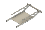
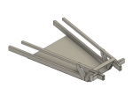
I was working on designing a new frame for the fall races, and I have a few questions.
My first question: Is this legal? All of square tubing is .125" thick aluminum and either 1x1 or a 1x2.
My second question: How do I make this smaller/lighter? Whenever I change to using less support or using 1x1s instead of 2x1s, it starts bending too much. I'm not very experienced with much of this at all really. Any advice would be great.
If you want to keep a design stiff, go with larger cross-section dimensions and use a thinner wall thickness to keep it light.
Try to fully triangulate the frame - this will greatly improve stiffness and strength.
If you are planning to use a heat-treated aluminium like 6061-T6, be aware that if you weld it, you will loose the heat treat in the weld area and reduce the strength by about 50%, which is significant. I prefer to avoid welding of aluminium and use glued/riveted joints instead (as in aircraft construction) but this does involve some engineering to do correctly.
You could look at aircraft and 1980's race car construction techniques for inspiration.
Is it legal? One of the reasons I think the Electrathon rule book is well written is it specifies end states rather than means.
3 FRAME / FRAME MEMBERS
1. All vehicles must have frame members that protect the driver in the event of collisions from any direction.
2. Frames may be constructed of various materials and styles providing that the material(s) or methods provide adequate structural strength for protection/safety. The design will need to be structurally sound in the opinion of inspectors and/or race officials.
So the choice of materials is up to you and the square tubing is legal if put together well.
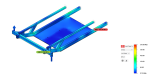
I am not clear of what you are testing in the images you posted but try breaking down each part and thinking about how flexible they are in isolation. The top of a 1 X 1 .125 square tube in isolation would be very flexible vertically but hard to flex horizontally. The longer the piece, the more it will flex.
Now think about compressing or stretching that length of flat aluminum. In each of these examples, we are only thinking about that one direction of force, not the obvious ways it would buckle in a real world test. In other words, if you try and compress this flat .125" one inch wide and, let's say 24" long piece of aluminum, it will normally fold up but for our thought experiment, it is fixed flat and we are only allowing the force to compress it. So, in effect, you are trying to compress a 24" thick piece of aluminum.
So if we can load our frame in a way that tries to compress (or stretch) our tubing, we will get more strength with less weight.
The Warren truss is a good example of how to achieve this. https://en.wikipedia.org/wiki/Warren_truss
When we talk of triangulate the frame, this is the concept behind it.
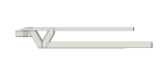
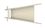
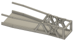
Thank you guys very much for the advice this time around. I decided to redesign it pretty much completely, and now it sits at just under 20 lbs (it was around 23 lbs last time). I'm going to be using rivets for this frame, and I triangulated a little bit, but not fully. I probably will add some more triangulation on the sides, like what ProEV suggested, but I'll see what happens.
My next question is: Should I considered pocketing any of these parts? I have access to a very nice cnc mill, and I know how to run commands to pocket the base plate or cut some of the triangulation bits out, but I'm not sure if I should.
First: excellent job w/ solid modeling and structural analysis!
I've been assuming you're showing the front end for a 2Front/1Rear 3-wheeler?
A couple thoughts going back to the rules/legality:
Have you checked against the size of a driver to make sure the top rail is 'tall' enough to meet EA rule 5.2 "...This body or structure needs to protect the driver's legs, feet, and side up to shoulder level protecting the rib cage from side impact."? I assume there will be more structure 'behind' what you've shown so far, but IDK if the driver's knees or feet would stick up too far to be protected.
Some more confirmation that 0.125 wall Al tube should be okay as a material: ChallengeUSA has rules very similar to EA but adds minimum specs for frame material "...The minimum size of all frame members that protect the driver (any frame member from the seat forward) and protect the batteries will be 1" OD round or 1" square tubing with the following wall thicknesses: [.0625" (16 gauge) for mild steel] [.058" for 4130 chromoly] [.083" for aluminum]"
The short version rather than post a lot of blather: before you go too far optimizing design details based on FEA, double check that your FEA uses realistic loads, boundaries, etc. Computer modeling can easily become Garbage In/ Garbage Out. This is not just trivia: bad modeling was one factor which ultimately resulted in the Space Shuttle SRB failure and the loss of the Challenger (it wasn't just the O-ring material).
Thank you for the advice again, and yes this is the front half of a 2front/1rear car.
1. Legality
Right now, from the top of the plate to the top of the square tubes is 7.2" and in the back of the plate is 24" I haven't designed the roll bar yet, but I'm checking the EA rule book along with the tighter regulations set out by the instructor (this is a high school team).
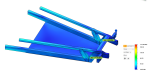
2. Simulations/Modeling
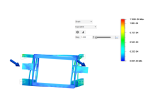
I run 3 simulations every time I want to check the stability of the car. The first one is a 2000N force pushing up on the 2x1 tube where the kingpin is going to be placed. I predict that when the car is just sitting it will have a force of roughly 750N on it, but I wanted to be sure it was stable when strongly cornering as well.
The second simulation is a 1000N force pushing back from the 2x1 tubing to test for buckling. I can't imagine why this one would be used, but it is free to run the simulation with an education account.
The third simulation is a crash test, where I push a force of 1000N straight backwards on basically every component on the front.
Thus far there hasn't been any issues with this, but if you think that there might be a force I'm not considering, I would be happy to run it.
I'll also upload some pictures when I get to my desktop, my little laptop can't handle that.
-- Edited by Bwo on Friday 23rd of February 2024 10:14:58 PM
Definitely check more of the effects from cornering. So far you have been applying loads in the 'x' axis (longitudinal) and 'z' axis (vertical), but nothing in the 'y' axis (lateral)?
Cornering forces act laterally at the tire contact patch.
Weight transfers to the outside wheel so you end up with asymmetric vertical loads. Basically, the lateral cornering force makes the car roll about its center of mass (and/or suspension, if the car has it...) until the outside wheel generates enough additional vertical force to counter the roll.
Combining the two effects and taking them to the limit, the inside wheel ends up with zero load (vertical or lateral: the inside wheel has no traction at all if it is barely skimming the ground or in the air) and the outside wheel provides all of the lateral cornering force plus all of the vertical force for the front end.
The obvious next questions: how much lateral load exactly, how much vertical load exactly, and how do you apply forces at the tire contact patch if you don't want to mess with adding wheels to the model of the chassis?
If you want a single reference to cite for loading, I think slide 23 basically says 2g lateral plus 2g vertical.
(skip over as much of the .pdf as you want. Some of the diagrams are not very clear, but generally it's not impossibly bad, and most importantly it was the first reasonable source I found online for free)
Complete personal opinion, I'd use 2.5g for both directions, and maybe add on 1g for braking.
If the software lets you apply loads offset from the actual structure, then life is easy. Otherwise, you could simply tack on a structural arm to represent the bottom of the wheel. The complicated way is to apply the lateral load to the chassis (at the height of the wheel spindle) along with a torque equal to the lateral load times the radius of the tire.
Other thoughts from some rando off the internet (I very likely may not actually know what I'm talking about, but it was taking a long time to double check everything)
If you are mounting batteries (or driver ballast) to the flat floor plate, start adding something to model the downward 'inertial' force resulting from the multiple-g upward force on the kingpins. Lead-acid batteries are a dense chunk of mass, 73# = 33kg, at 2.5-3g ends up 800-900N.
(side comment: if you are not mounting your batteries that far forward, even lithium, have y'all done some checks on CG location vs. stability for a 3-wheeler?)
Crash testing is a big approximation, and it takes a completely different type of simulation to do it very accurately. Once you have more of the chassis modeled, maybe try reversing the loads and anchors instead of what you are doing now. We'd be saying that in a crash the front of the chassis stops 'instantly' in contact w/ whatever object was hit, everything else in the car tries to keep moving due to inertia, and the chassis provides deceleration forces thru the various mounting points.
Anchor the front of the chassis (the entire width to hit a wall, only a narrow section to hit a pole)
figure out the force of the driver's mass * g's of crash deceleration, then divide up that load across the driver harness mounting points. (note: try to use these numbers to justify getting a 6-point harness with "formula car" or "d-ring" style anti-submarine straps. 2nd choice is a "FIA" style 6-point.)
Do the same thing for the mass of the batteries and their mounting points, plus any driver ballast, and maybe the motor.
This approach does ignore the mass of the chassis itself. Again it's an approximation, but it will give a slightly better idea what happens with the chassis around the driver (and other heavy stuff like batteries) which is the most important thing. Simulating a side impact or roll-over could be done more or less the same way: anchor whatever section of the chassis you want to say gets hit, then apply 'inertial' loads for the components in the appropriate direction.
Sorry it took so long to reply, when I got to my desktop, I figured out that the tech department had blocked the forums. It took a couple days to convince tech to let me back on. Anyways, thank you for the advice again, and I'd say 0apfu is pretty much right about everything.
1. Simulations
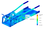
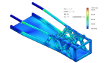
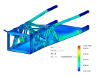
I've pretty much redid all of my testing according to what you suggested and what the document said. I estimated that the car would weigh 500 lbs for my calculations. Thus the forces are
2000N-Force of gravity 3000N-Force of cornering 2000N-Force of braking
Then with those numbers, I run 4 simulations, one with each force and one with all three at the same time.
2. Design changes
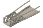
Looking back at this topic, I realize I haven't update what the car looks like in quite a bit. I did look at stability based off of the center of gravity, and it was really bad. I then added some more room for the driver in the front and pushed the CG forward. I also added a step for the base plate, added some better triangulation and worked on the top plate again. I haven't made the steering system, nor did I approximate it like 0apfu suggested. Right now the next thing I am going to do is some crash testing, and change the design a little bit if things go too poorly.
Some more info about the images: if it has "adjusted" in the name, that means the deformations are scaled up for visibility. "worst case" is when I used all three of those forces above.